Arduino Uno Gas Alert System with MQ135 Sensor, Buzzer, and LEDs (Red and Green) Project Report
Project Title: Gas Alert System using MQ135, Arduino UNO, Buzzer, and LEDs for HP International School, Badaun
1. Introduction
In this project, we aim to design and implement a gas alert system using an MQ135 gas sensor, an Arduino Uno microcontroller, a buzzer, and LEDs. The system will be used to detect the presence of harmful gases in the environment, triggering visual and audible alerts when the gas concentration exceeds safe limits. This system is crucial for ensuring safety in areas where gases like ammonia, smoke, CO2, or alcohol could pose health hazards.
The system will feature a red LED for dangerous gas levels, a green LED for safe conditions, and a buzzer that will sound when hazardous gas levels are detected. This design will help provide early warnings to prevent potential accidents.
2. Components Used
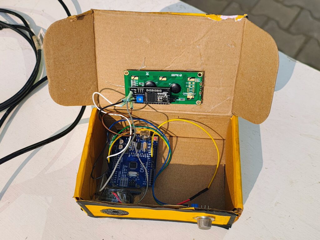
- Arduino Uno: The microcontroller that controls the entire system.
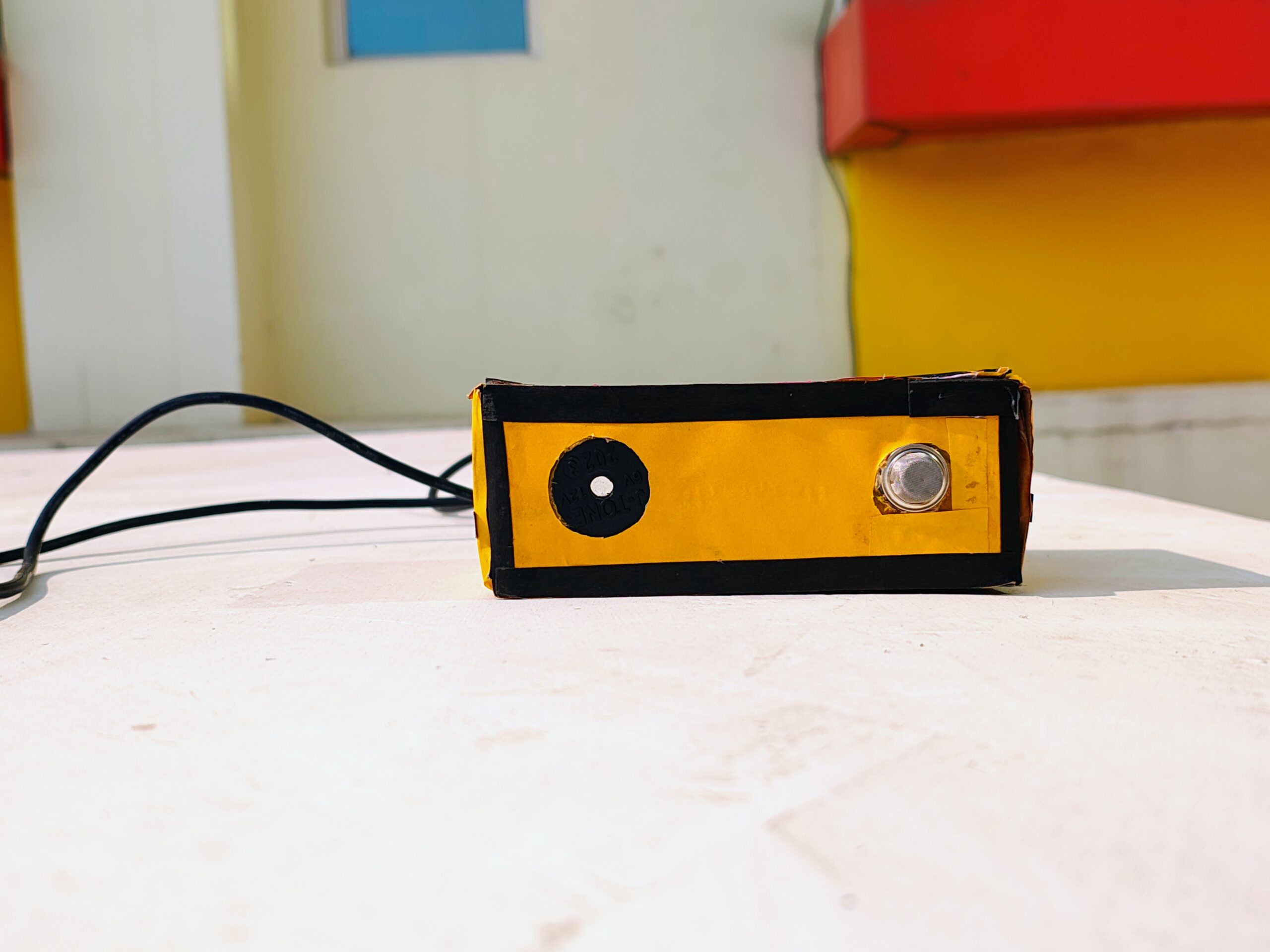
- MQ135 Gas Sensor: A sensor that detects harmful gases such as ammonia (NH3), carbon dioxide (CO2), alcohol, and smoke.
- Red LED: A visual indicator that signals dangerous gas levels.
- Green LED: A visual indicator that signals safe gas levels.
- Buzzer: An audio alarm that sounds when gas levels exceed a predefined threshold.
- Resistors (220Ω for LEDs, 10kΩ for sensor): Used to limit current to prevent damage to components.
- Breadboard and Jumper Wires: For connecting all components.
- Power Supply (5V): For powering the Arduino and connected components.
3. Circuit Diagram
Below is the typical connection layout:
- MQ135 Gas Sensor:
- VCC to 5V on Arduino
- GND to GND on Arduino
- A0 (analog output) to an analog pin (A0) on Arduino
- Red LED:
- Anode (+) to a digital pin (D2) on Arduino
- Cathode (-) to GND through a 220Ω resistor
- Green LED:
- Anode (+) to a digital pin (D3) on Arduino
- Cathode (-) to GND through a 220Ω resistor
- Buzzer:
- Positive terminal to digital pin (D4) on Arduino
- Negative terminal to GND
4. Working Principle
- Gas Detection: The MQ135 sensor continuously monitors the surrounding air for harmful gases. It provides an analog output voltage that corresponds to the concentration of gases detected. The higher the concentration of harmful gases, the higher the sensor’s analog output voltage.
- Threshold Comparison: The Arduino reads the output of the MQ135 sensor through the analog input pin. It compares this sensor value to a predefined threshold to determine whether the gas concentration is within safe limits or if it has exceeded the critical level.
- Output:
- If the gas concentration is within safe limits, the green LED lights up to indicate safety.
If the gas concentration exceeds the threshold, the red LED turns on, and the buzzer emits a sound, alerting people to the danger.
5. Code
#include <Wire.h> // Include the Wire library for I2C
#include <LiquidCrystal_I2C.h> // Include the LiquidCrystal I2C library
// I2C address of the LCD (0x27 is common, but it can vary)
LiquidCrystal_I2C lcd(0x27, 16, 2); // 16 columns and 2 rows
int redLed = 10;
int greenLed = 12;
int buzzer = 8;
int smokeA0 = A0;
int sensorThres = 50; // Threshold for smoke percentage (adjustable)
void setup() {
pinMode(redLed, OUTPUT);
pinMode(greenLed, OUTPUT);
pinMode(buzzer, OUTPUT);
pinMode(smokeA0, INPUT);
Serial.begin(9600);
// Initialize the LCD
lcd.begin(16, 2); // Initialize the LCD with 16 columns and 2 rows
lcd.backlight(); // Turn on the backlight
lcd.setCursor(0, 0); // Move the cursor to the first row, first column
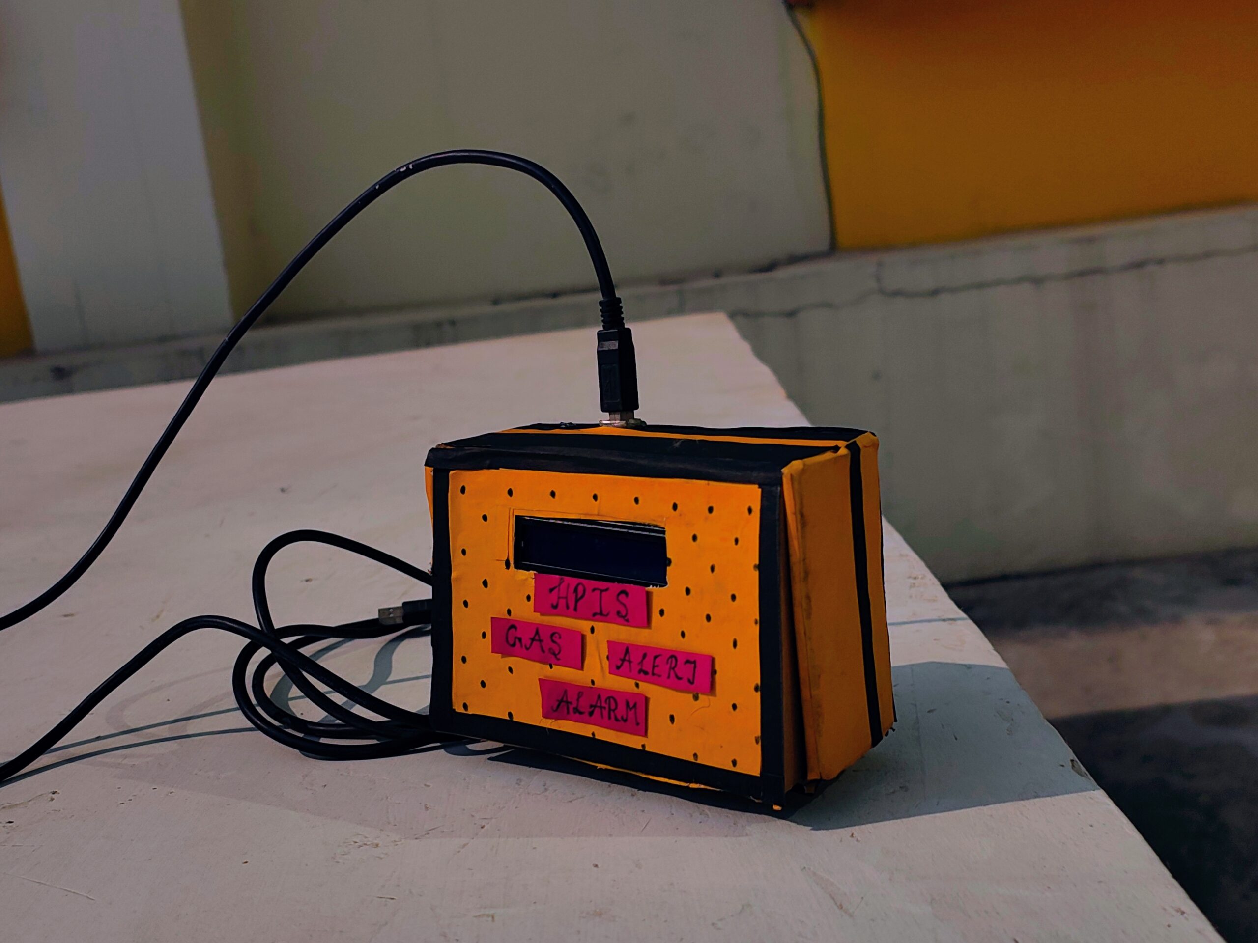
lcd.print(” HPIS GAS ALARM”); // Display initial message
}
void loop() {
int analogSensor = analogRead(smokeA0); // Read analog value from the smoke sensor
int smokePercentage = map(analogSensor, 0, 1023, 0, 100); // Map sensor value to percentage
// Debugging info via Serial Monitor
Serial.print(“Pin A0: “);
Serial.println(analogSensor);
// Clear the second row of the LCD before printing the updated percentage
lcd.setCursor(0, 1); // Move to the second line
lcd.print(” “); // Clear the second line by printing spaces
// Display the smoke percentage on the second row
lcd.setCursor(0, 1); // Move cursor back to second line
lcd.print(“Level: “);
lcd.print(smokePercentage); // Display the smoke level as percentage
lcd.print(“%”); // Add the percentage symbol
// Check if the smoke level exceeds the threshold
if (smokePercentage > sensorThres) {
digitalWrite(redLed, HIGH); // Turn on the red LED
digitalWrite(greenLed, LOW); // Turn off the green LED
tone(buzzer, 1000, 200); // Sound the buzzer for 200ms
lcd.setCursor(0, 1); // Reposition the cursor to update the message
lcd.print(“Alert! GAS! LEAK!”); // Display alert message
} else {
digitalWrite(redLed, LOW); // Turn off the red LED
digitalWrite(greenLed, HIGH); // Turn on the green LED
noTone(buzzer); // Stop the buzzer
lcd.setCursor(0, 1); // Reposition the cursor
lcd.print(“Normal. No LEAK!.”); // Display normal message
}
delay(500); // Delay for readability
}
6. Working of the Code
- Sensor Reading: The code reads the analog value from the MQ135 sensor using analogRead(mq135Pin). This value is proportional to the concentration of gases detected by the sensor.
- Threshold Check: If the sensor value exceeds the set threshold (in this case, 400), the system considers it dangerous and activates the red LED and buzzer. If the value is below the threshold, the green LED lights up, indicating safe conditions.
- Serial Monitor: For debugging purposes, the sensor readings are printed to the serial monitor.
7. Testing and Calibration
Before deploying the system in a real-world environment, it is essential to calibrate the MQ135 sensor to ensure accurate gas detection. Calibration involves adjusting the threshold value based on real gas concentrations in the testing environment. The sensor may take some time to warm up and provide accurate readings after powering on, typically requiring 24–48 hours for full calibration.
8. Applications
- Schools and Educational Institutions: The gas detection system can be used in laboratories and classrooms where chemicals are stored.
- Factories: In industries that deal with hazardous gases, this system can alert workers to dangerous gas levels.
- Households: It can be used to monitor the air quality in homes, particularly in kitchens and areas with gas appliances.
9. Conclusion
This Gas Alert System using MQ135, Arduino Uno, and other peripheral components is an efficient way to ensure safety by providing immediate alerts in the event of dangerous gas concentrations. By detecting hazardous gases in real time and triggering visual and audio alarms, this system can play a critical role in safeguarding people from potential gas hazards in environments such as HP International School, Badaun.
10. Future Improvements
- Mobile App Integration: Implement a mobile app to receive alerts remotely.
- Wireless Communication: Use technologies like Bluetooth or Wi-Fi for wireless data transmission to a monitoring system.
- Multiple Sensors: Integrate additional sensors (e.g., for smoke, CO) for more comprehensive safety monitoring.
References:
- Arduino Official Documentation (https://www.arduino.cc/)
- MQ135 Gas Sensor Datasheet (https://www.winsen-sensor.com/d/ds-mq135.pdf)
This report provides an overview of the gas alert system, its components, working principle, and applications, along with the necessary code and hardware setup for implementation.
Leave a Reply